
hi all ive been thinking about a potential problem i might have here.
in this post http://www.v8forum.co.uk/forum/viewtopic.php?t=150 its stated i need to put a lead on the -ve of the coil to trigger the efi. now with MJ i wont have a -ve on the coil.
how the hell do i make the efi fire?
megajolt and flapper efi
Moderator: phpBB2 - Administrators
Re: megajolt and flapper efi
Are you using multiple coils? Normal way would be to take a feed from each coil LT negative via a diode, link the outputs of the diodes, then feed that to the ECU via the normal resistor.karlos01 wrote:hi all ive been thinking about a potential problem i might have here.
in this post http://www.v8forum.co.uk/forum/viewtopic.php?t=150 its stated i need to put a lead on the -ve of the coil to trigger the efi. now with MJ i wont have a -ve on the coil.
how the hell do i make the efi fire?
But surely this is covered in the MJ manual?
Dave
London SW
Rover SD1 VDP EFI
MegaSquirt2 V3
EDIS8
Tech Edge 2Y
London SW
Rover SD1 VDP EFI
MegaSquirt2 V3
EDIS8
Tech Edge 2Y
Can you post a link to the MegaJolt wiring diagram you're using?karlos01 wrote:right ive come to wire it all together now, looking for the wire to feed the efi. i dont appear to have it at all.
can this be right?
Might it be called 'tach'? This seems to be the US terminology for an ignition feed to the injection.
Dave
London SW
Rover SD1 VDP EFI
MegaSquirt2 V3
EDIS8
Tech Edge 2Y
London SW
Rover SD1 VDP EFI
MegaSquirt2 V3
EDIS8
Tech Edge 2Y
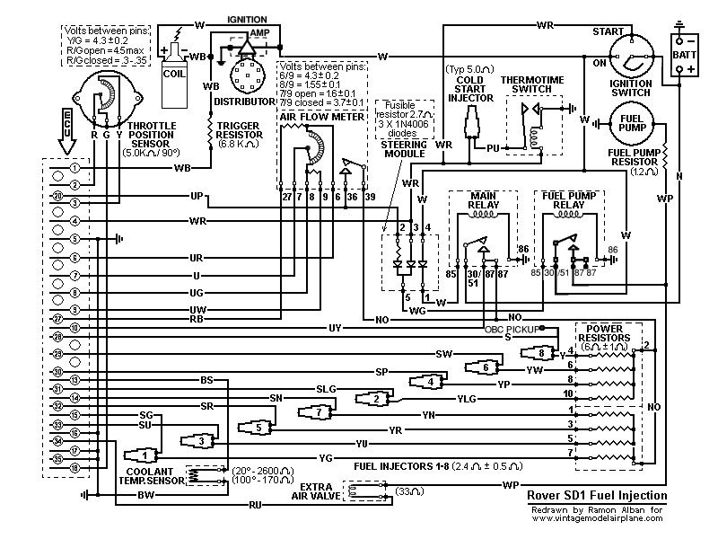
Originally, it would be a parallel wire from the coil negative via a resistor. Colour is white/black. Goes to pin1 of the ECU. The resistor value is 6800 ohms.karlos01 wrote:na i mean i have got that bit sussed, the range rover flapper loom doesnt have the supposed wire. ive got a relay with a couple of wires on it that doesnt appear to go anywhere but no wire that is supposed to set the efi to go
There are two relays - one for ECU power (main), and one for the pump. Note the main relay is a twin output type rather than the more usual SPDT 5 pin ones. As per the factory, the pump one utilises the same type of relay, but a SPDT type can be used instead.
Dave
London SW
Rover SD1 VDP EFI
MegaSquirt2 V3
EDIS8
Tech Edge 2Y
London SW
Rover SD1 VDP EFI
MegaSquirt2 V3
EDIS8
Tech Edge 2Y


Is that a custom made loom? It doesn't look like a factory one. You'd also need to say what the wire colours are if a factory loom - your pics don't show that here.
As I said, the ignition feed (ie tach) to the injection comes from the coil negative on a flappper system via a resistor and goes direct to the ECU. Nowhere near a relay. The red diode pack (steering module) on the flapper system is for pump control.
As I said, the ignition feed (ie tach) to the injection comes from the coil negative on a flappper system via a resistor and goes direct to the ECU. Nowhere near a relay. The red diode pack (steering module) on the flapper system is for pump control.
Dave
London SW
Rover SD1 VDP EFI
MegaSquirt2 V3
EDIS8
Tech Edge 2Y
London SW
Rover SD1 VDP EFI
MegaSquirt2 V3
EDIS8
Tech Edge 2Y
it is 100% guaranteed factory loomfrom an 89 range rover.
that little lot is sprouting from the loom near the afm area. definately a flapper loom and definately a factory one.
the wire colours are black, black and white, white and coming off the relay, blue and white
the other relays are iin the car as is the diode pack
that little lot is sprouting from the loom near the afm area. definately a flapper loom and definately a factory one.
the wire colours are black, black and white, white and coming off the relay, blue and white
the other relays are iin the car as is the diode pack
-
ramon alban
- Knows His Stuff

- Posts: 667
- Joined: Fri Nov 17, 2006 11:22 pm
- Location: Bedford UK
- Contact:
Hello Karlos,
Actually, what you have in your hand is the Range Rover/Land Rover Flapper System "overrun fuel shut off relay" which works in conjunction with a vacuum switch.
This is a different system to the mechanical vacuum valve fitted to the Rover SD1 Efi system.
Their purpose is to shut off injector operation during high manifold vacuum that occurs when decelerating from high speed with throttle closed.
With ignition on, the relay is energised via the vacuum switch and the white wire with the black wire connected to earth
With low vacuum, and the relay energised, coil negative is connected to the relay contacts via a 6800 ohm resistor and the white/blue wire.
The other closed contact on the relay goes to pin 1 of the ECU via white/black wire.
Thus connected the ECU is able to operate the injectors.
When on overrun, and with high vacuum, the relay is de-energised, the contacts open, the running signal from coil negative is disconnected from pin 1 of the ECU and the injectors cease to operate.
The advantages are improved economy and reduced emissions.
